


SCT o13 ADS1115 Pinout to ESP32: Complete Guide 2026
-
Onstipes / 1 month
- December 7, 2025
- 0
- 11 min read
Connecting the SCT-013 current sensor with the ADS1115 ADC module and an ESP32 is a reliable way to achieve accurate AC current measurements in DIY and IoT projects. Because the ESP32 has limited analog resolution, pairing it with the ADS1115 16-bit ADC delivers cleaner, more precise readings—especially when dealing with low-current signals. This setup is commonly used in home energy monitoring, smart power meters, and industrial automation.
Understanding the SCT-013 to ADS1115 pinout is essential before wiring everything to the ESP32. A correct connection not only prevents calibration issues but also ensures stable sensor output, better noise handling, and overall safe measurement.
What Is the SCT-013 Current Sensor and How It Works?
The SCT-013 current transformer is a non-invasive AC current sensor used to measure electrical load without cutting wires. It works by detecting magnetic flux around a conductor and producing a small output signal. When paired with the ADS1115 ADC, it delivers accurate current readings for ESP32-based energy monitoring projects.
The sensor outputs a voltage proportional to the current flow, making it ideal for applications like home power tracking, smart meters, and industrial monitoring. Because the SCT-013 requires proper biasing and calibration, integrating it with a 16-bit ADS1115 converter significantly improves measurement stability and reduces signal noise.
When used with the ESP32, the SCT-013 benefits from higher resolution conversion, cleaner analog sampling, and better real-time data accuracy. Understanding its internal working principle, sensitivity rating, and recommended SCT-013 to ADS1115 pinout helps prevent reading fluctuations, distorted waveforms, and incorrect current calculations in your circuit.
Overview of ADS1115 16-Bit ADC and Why It’s Needed
The ADS1115 16-bit ADC provides high-resolution analog-to-digital conversion, making it essential when using sensors like the SCT-013 that produce small analog signals. Since the ESP32 ADC often introduces noise and inconsistent readings, the ADS1115 ensures stable, accurate current measurements for energy monitoring and IoT projects.
This ADC includes programmable gain amplification (PGA), allowing you to amplify low-level signals from the SCT-013 CT sensor. Features like I2C communication, differential input modes, and wide voltage ranges make the ADS1115 module reliable when integrating precise analog sensors with microcontrollers such as the ESP32.
Using the ADS1115 with the SCT-013 to ESP32 wiring setup gives you clean sampling, better calibration control, and improved waveform accuracy. It helps eliminate issues like signal clipping, ADC saturation, and reading fluctuations. This makes the ADS1115 a preferred solution for current sensing, power monitoring, and other real-time measurement applications.
Why Use the ESP32 for Current and Power Monitoring?
The ESP32 is widely used for current and power monitoring because it offers Wi-Fi, Bluetooth, fast processing, and low-power performance. When combined with the ADS1115 and SCT-013 current sensor, it becomes a powerful platform for building smart energy meters and real-time monitoring dashboards.
The ESP32’s built-in ADC often struggles with noise, making the ADS1115 16-bit ADC essential for clean readings. This combination helps capture accurate AC current waveforms, supports calibration adjustments, and enhances overall measurement precision. It’s especially useful in IoT automation, renewable energy tracking, and home efficiency systems.
Pairing the SCT-013 to ADS1115 pinout with the ESP32 ensures a stable signal path and prevents distortions. This setup improves data logging, cloud reporting, and continuous monitoring without losing accuracy. Its flexibility allows users to build scalable systems for both hobby projects and professional-grade measurement solutions.
Required Components and Wiring Essentials
To set up accurate current measurement, you need an SCT-013 current sensor, an ADS1115 16-bit ADC module, and an ESP32 board. Additional components like resistors, capacitors, and optional pull-up resistors ensure stable I2C communication and clean analog signals, preventing errors in readings and protecting your circuit.
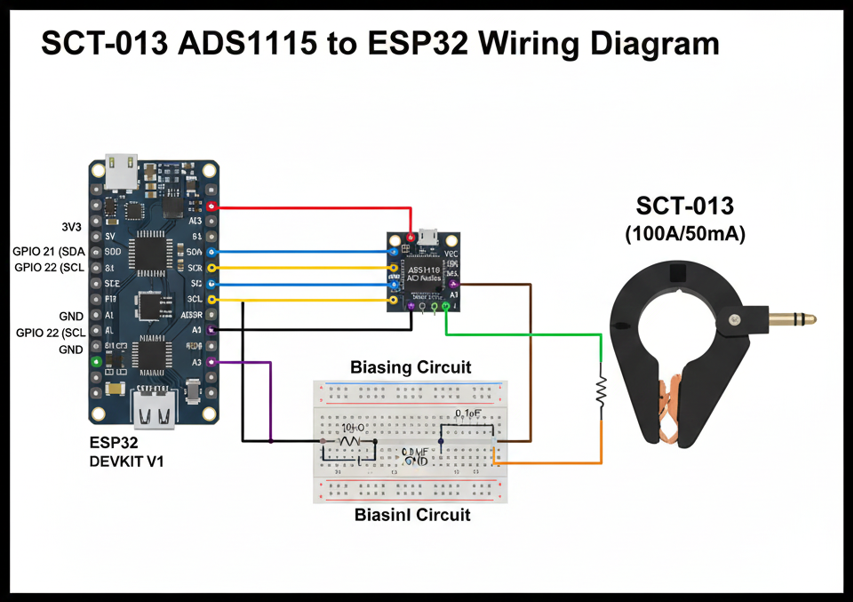
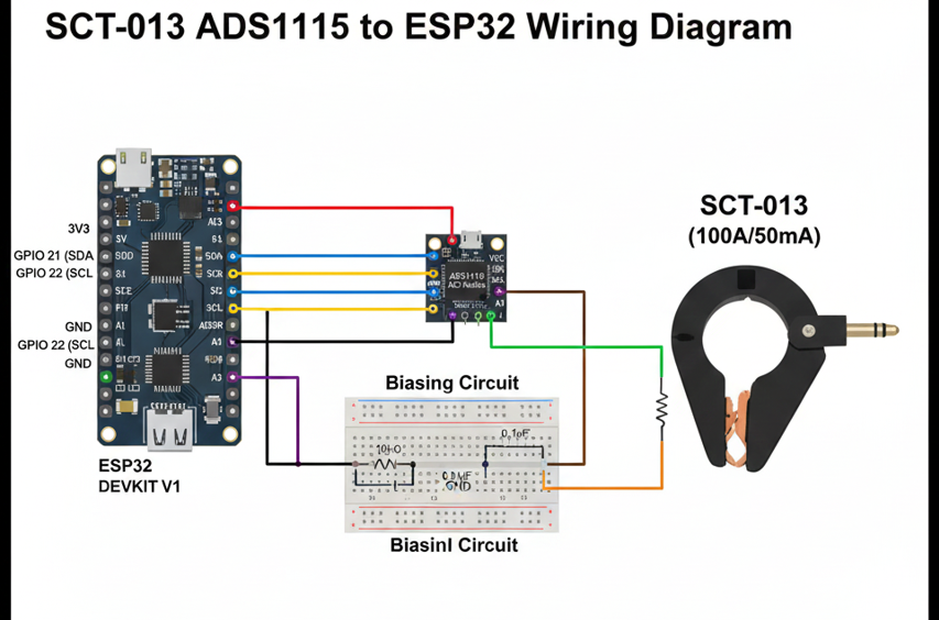
It’s important to understand the SCT-013 to ADS1115 pinout before wiring. Connect the sensor’s output to the differential inputs of the ADS1115, set proper biasing, and link the module’s SDA/SCL pins to ESP32’s I2C pins (GPIO21 & GPIO22). Correct wiring ensures accurate readings and avoids sensor misbehavior or noisy signals.
Other optional components, like a burden resistor or low-pass filter, improve measurement stability. Proper component selection, combined with correct ESP32 and ADS1115 integration, guarantees reliable AC current sensing. This foundational setup is crucial before writing code or attempting calibration, providing a safe and precise base for your project.
Understanding the SCT-013 to ADS1115 Pinout
The SCT-013 current sensor has two output wires that must connect correctly to the ADS1115 differential input pins. Knowing the correct SCT-013 to ADS1115 pinout ensures the ESP32 receives accurate analog signals without errors, making calibration and RMS calculations reliable for AC current measurement projects.
The ADS1115 features four input pins (A0–A3) and supports differential or single-ended readings. For SCT-013 integration, A0 and A1 are commonly used as differential inputs. Proper connection of SDA and SCL pins to ESP32 I2C lines (GPIO21 and GPIO22) ensures stable communication and prevents reading fluctuations caused by wiring mistakes or noise interference.
Additionally, powering the ADS1115 correctly (VDD to 3.3V and GND to ESP32 ground) and configuring the ADDR pin properly allows multiple ADS1115 modules on the same I2C bus. Understanding these pinout details is essential to avoid sensor misreading, signal clipping, and ensures smooth operation in real-time current monitoring.
Burden Resistor: Purpose and Calculation
The burden resistor converts the SCT-013’s current output into a measurable voltage for the ADS1115 ADC. Selecting the correct resistor value ensures the voltage stays within the ADC’s input range. Using a wrong burden resistor can cause saturation, inaccurate readings, or distorted waveforms when connected to the ESP32.
To calculate the proper burden resistor, consider the SCT-013 rating and maximum current. Use the formula R = Vmax / Imax, where Vmax is the ADC’s voltage limit and Imax is the sensor’s maximum current. This ensures the differential input of the ADS1115 receives safe, proportional voltage from the SCT-013.
Using the burden resistor along with a proper bias circuit stabilizes the AC waveform, enabling accurate RMS current calculations. Correct resistor selection improves overall measurement accuracy, reduces noise, and protects the ESP32 and ADS1115 from potential overvoltage, making your current sensing setup reliable and precise.
Bias Circuit: Why It’s Needed and How to Build One
The bias circuit offsets the AC signal from the SCT-013 to a mid-rail voltage, allowing the ADS1115 16-bit ADC to measure both positive and negative cycles. Without biasing, the ADC cannot read negative voltages, leading to incorrect current measurements with the ESP32.
A simple bias circuit uses a resistor voltage divider to create a 1.65V mid-rail and a capacitor for signal smoothing. Connecting this between the SCT-013 output and ADS1115 differential inputs ensures the waveform stays within safe voltage limits while preserving accuracy for RMS and real-time monitoring.
Properly implementing the bias circuit along with the SCT-013 to ADS1115 pinout improves signal integrity and reduces noise. This setup is essential for stable readings, reliable calibration, and safe operation, providing a strong foundation before moving on to writing the ESP32 code and performing RMS calculations.
ESP32 Code for Reading ADS1115 and SCT-013
To read AC current from the SCT-013 using ADS1115 with ESP32, start by initializing I²C communication on GPIO21 (SDA) and GPIO22 (SCL). Configure the ADS1115 with appropriate gain and differential mode to handle the small voltage output from the current transformer accurately.
Once initialized, read the raw ADC values from the differential inputs connected to the SCT-013. Apply the bias offset to shift the waveform around zero and store multiple samples for averaging. This reduces noise and ensures accurate real-time measurements suitable for energy monitoring projects and IoT dashboards.
Finally, convert the ADC voltage readings into current using the SCT-013 rating and burden resistor value. Implement RMS calculation or simple averaging depending on your project needs. Properly calibrated, this ESP32 ADS1115 SCT-013 setup delivers precise AC current measurements for home or industrial applications.
RMS Calculation and Converting ADC Readings to Current
After collecting ADC values from the ADS1115, calculate the RMS current to obtain meaningful AC measurements. Square each sample, compute the average, and then take the square root. Using the SCT-013 rating and burden resistor, convert voltage readings into actual current values for ESP32 monitoring projects.
For improved accuracy, consider sampling at a rate high enough to capture the 50/60Hz AC waveform. Apply averaging or filtering techniques to smooth the data and reduce noise. This ensures that the SCT-013 to ADS1115 pinout and bias circuit deliver clean readings suitable for energy meters and IoT applications.
Calibrating the RMS calculation using a known load allows you to fine-tune your measurements. Adjust the scaling factor based on actual results to match expected current values. With correct calibration, the ESP32 ADS1115 SCT-013 setup provides precise, reliable real-time AC current monitoring for home, industrial, or DIY projects.
Also Read: Enter Password to Unlock 30 30 Attempts Remaining
Accuracy Optimization Tips for SCT-013 and ADS1115
Choosing the correct ADS1115 gain is crucial for accurate readings with the SCT-013. High gain improves sensitivity for low-current measurements, while too high can cause saturation. Proper gain settings combined with the ESP32 ensure precise data for AC current monitoring and energy measurement projects.
Reducing electrical noise improves accuracy. Use short, shielded wires, proper grounding, and a bias circuit to stabilize the signal. Implement software averaging or low-pass filtering on the ESP32 to minimize fluctuations. These practices ensure clean readings from the SCT-013 to ADS1115 pinout, preventing distorted waveforms or incorrect RMS calculations.
Correct placement of the burden resistor, biasing, and calibration further enhances reliability. Avoid overloading the SCT-013 and ensure the differential input voltage never exceeds ADS1115 limits. Following these steps guarantees stable, accurate, and repeatable current measurements, making your ESP32-based system highly dependable for energy monitoring and IoT applications.
Common Issues and Troubleshooting
Sometimes the SCT-013 may produce fluctuating or incorrect readings when connected to the ADS1115 and ESP32. This is often caused by wiring errors, incorrect bias voltage, or using the wrong burden resistor. Double-checking the SCT-013 to ADS1115 pinout usually resolves most common issues.
Noisy readings can result from long wires, electromagnetic interference, or improper grounding. Using shielded cables, keeping connections short, and implementing a bias circuit help maintain signal integrity. Applying software averaging or filtering in your ESP32 code also reduces measurement noise and improves RMS current calculation accuracy.
Other issues include ADC saturation due to high current, incorrect gain settings, or I²C communication conflicts. Verifying calibration with a known load ensures reliable measurements. Following these troubleshooting steps ensures your ESP32 ADS1115 SCT-013 setup functions consistently and delivers precise current readings for energy monitoring applications.
Advanced Project: ESP32 Home Energy Monitor Using SCT-013 and ADS1115
Combining the SCT-013 current sensor, ADS1115 ADC, and ESP32 allows you to build a complete home energy monitoring system. This setup can measure individual appliance usage, track real-time energy consumption, and send data to dashboards or cloud platforms for analysis and automation.
By integrating RMS calculations and calibration, your ESP32 can accurately report AC current and power usage. Using multiple SCT-013 sensors with several ADS1115 modules lets you monitor different circuits simultaneously. Correct wiring, biasing, and gain configuration ensures reliable, long-term operation without signal distortion or data loss.
This advanced setup also enables smart home applications. You can trigger alerts for high energy usage, log historical data, or connect to Home Assistant or MQTT-based dashboards. Such projects transform simple ESP32 current monitoring into a professional-grade energy management system for homes or small businesses.
Safety Guidelines for Using SCT-013 and ADS1115 with ESP32
Although the SCT-013 current sensor is non-invasive, always handle AC wiring carefully to avoid electrical hazards. Ensure proper insulation, secure connections, and avoid touching live wires. Correctly connecting the SCT-013 to ADS1115 pinout prevents short circuits and protects both the ESP32 and sensors.
Use a properly rated burden resistor to prevent overheating and overvoltage. Make sure all components are rated for your measurement range. Placing the ADS1115 and ESP32 on a well-ventilated surface reduces heat buildup, ensuring safe and stable operation for long-term current sensing applications.
Avoid running wires near high-power devices or sources of electromagnetic interference. Shielding, proper grounding, and keeping sensor cables short will improve measurement accuracy. Following these safety practices guarantees reliable operation of your ESP32 ADS1115 SCT-013 setup while protecting both users and electronic components.
Final Summary and Downloadable Resources
Integrating the SCT-013 current sensor, ADS1115 16-bit ADC, and ESP32 creates a precise, reliable AC current measurement system. Correct wiring, biasing, and calibration ensure accurate readings for RMS current, energy monitoring, and smart home projects. Following all steps prevents noise and saturation issues.
By implementing proper SCT-013 to ADS1115 pinout, gain configuration, and RMS calculation, your ESP32 setup delivers clean, real-time data. Troubleshooting tips, optimized code, and accuracy improvements make it suitable for both beginners and advanced users aiming for professional energy monitoring solutions.
For convenience, downloadable resources such as wiring diagrams, full Arduino/ESP32 code, calibration spreadsheets, and bias circuit schematics are recommended. Using these resources with your project ensures a smoother setup, faster development, and more reliable results when building your ESP32 ADS1115 SCT-013 energy monitoring system.